telephone cables
So let's say you're working on a household project and need around a dozen telephone cables---the ordinary kind that you would use between your telephone and the wall. It is, of course, more cost effective to buy bulk cable, or simply a long cable, and cut it to length and attach jacks yourself. This is even mercifully easy for telephone cable, as the wires come out of the flat cable jacket in the same order they go into the modular connector. No fiddly straightening and rearranging, you can just cut off the jacket and shove it into the jack.
But, wait, what's up with that whole thing anyway? and are telephone cables really as simple as stripping the jacket and shoving them in?
There's a lot of weirdness about modular cables. I use modular cable to refer to a cable assembly that is terminated in modular connectors, a standard type of multipin connector developed by the Bell System in the 1960s and now widely used for telephones, Ethernet, and occasionally other applications. These types of connectors are often referred to as RJ connectors, although that's a bit problematic for the pedantic. The modular connector itself is more properly designated in terms of its positions and contacts. Telephone connections predominantly use a 6P4C modular connector: the connector has six positions, but only four are populated with actual contacts. Ethernet uses an 8P8C modular connector, a bit larger with eight positions, all of which are used. The handset of a telephone typically connects to the base with a 4P4C connector: smaller than the 6P4C, but still with four contacts.
Why? And what do the RJ designations actually have to do with it?
Well, historically, telephones would be hardwired to the wall by the telephone installer. This proved inconvenient, and so the connection between the telephone and wall started to be connectorized. Telephones of the early 20th century were unlike the ones we use today, though, and were not fully self contained. A "desk set," the part of the telephone that sat on your desk, would be connected to an electrical box, usually mounted on the wall. The box was often called the ringer box, because it contained the ringer, but in many cases it also contained the hybrid transformer that achieved the telephone's key feat of magic: the combination of bidirectional signals onto one wire pair.
The hybrid transformer performed the conversion between a two-wire (one pair) signal and a four-wire (two-pair) signal with 'talk' and 'listen' on separate circuits. Since the hybrid was in the box on the wall, the telephone needed to be connected to the box by four wires. Thus the first standard telephone connector, a chunky block with protruding pins, had four contacts. These connectors were in use even after the end of separate ringer boxes, making two of the four wires vestigial. They were still in use into the 1960s, and so you might still find them in older houses.
As you will gather from the fact that the hybrid may have been in the phone or in a box on the wall, and thus the telephone connection to the wall may require four or two wires, the interface between telephone and wall was poorly standardized. This wasn't much of a problem in practice: at the time, you did not own a telephone, you rented it. When you rented a phone, an installer would be sent to your house, and if any wiring was already present they would check it and adjust the connections as required. Depending on the specific type of service you had, the type of phone you had, and when it was all installed, there were a number of ways things might actually be connected.
By the 1950s, as the Model 500 telephone became the norm, a separate hybrid became very unusual: the Model 500 had a hybrid built into its base and only needed the two wires, which could be connected directly to the exchange without an intermediary box. So what of the other two wires? Just about anyone will tell you that the other two wires are present to allow for a second telephone line. This isn't wrong in the modern context, but it is ahistorical to the origin of the wiring convention. The four wires originated with the use of an external hybrid, and when they became vestigial, other uses were sometimes found for them.
For example, the "Princess" phone, a rather slick phone introduced as more of a consumer-friendly product in 1959, had a cool new feature: a lighted dial. The Princess phone was advertised specifically for home use, and particularly as a bedside telephone, so the lighted dial was a convenient feature if you wanted to make a telephone call at night. I realize that might sound a bit strange to the modern reader, but a lot of people used to put a phone extension on their nightstand. If you wanted to place a call after you had turned out the lights, wouldn't it be nice to not have to get up and turn them back on just to see the dial? Anyway, the whole concept of the Princess phone was this kind of dialing-in-bed luxury, and the glowing dial was a nice touch.
There's a problem, though: how to power the dial light? It could potentially be powered by the loop current, but the loop current is very small, likely to be split across multiple extensions, and the exchange would not appreciate the increased load of a lot of tiny dial lights. Instead, Princess phones were installed with a transformer that produced 6VAC from wall power for the dial light. That power was delivered to the phone using the two unused wires in its wall connection. This sounds rather slick in the era of DECT phones that require a separate power cable to the wall, and was one of the upsides of the complete integration of the telephone system. One of the downsides was, of course, that you were paying a monthly rental rate for all of this convenience.
In the late 1960s, the nature of telephone ownership radically changed. A series of judicial and regulatory decisions, culminating in the Carterfone decision, unleashed the telephone itself from the phone company. In the 1970s, consumers gained the ability to purchase their own phone and connect it to the telephone network without a rental fee. Increasingly, they chose to do so. Suddenly, the loose standardization of the telephone-to-wall interface became a very real problem, and one that impeded the ability of consumers to choose their own telephone.
The solution was the Registered Jack, originally a set of standardized wiring configurations developed within the Bell System and later a matter of federal regulation. Wiring installed by telephone companies was required to provide a standard Registered Jack so that consumers could easily connect their own device. It is important to understand that the Registered Jack standards are really about wiring, not connectors. They describe the way that connectors should be wired to meet specific standard applications.
The most straightforward is number 11, RJ11, which specifies a 6P2C connector with a single telephone pair. But what of the 6P4C connector we use today? Well, that's RJ14, a 6P4C with two telephone lines. The problem is that neither consumers nor the telephone cable industry have much of any appetite for understanding these distinctions, and so today the RJ standards have become misunderstood to such a degree that they are only poor synonyms for the modular jack configuration.
Cables with 6P4C connectors are routinely advertised as RJ11 or RJ14, sometimes RJ11/RJ14. Most of the time RJ11 is manifestly incorrect as they do, in fact, contain four wires and thus provide 6P4C connectors. Actual 6P2C telephone cables are uncommon, as they don't really cost any less than 6P4C (manufacturing cost by far dominating the small-gauge copper) and consumers tend to expect any telephone cable to work with a two-line phone. RJ14 here is even incorrect, as there really is no such thing as an RJ14 cable. It's in the name, Registered Jack: RJ14 describes the jack you plug the cable into, the electrical interface presented on the wall. Any 6P4C cable could be used with any RJ that specifies a 6P4C connector. Incidentally, this is only academic, as RJ14 is the only 6P4C jack. This is, of course, much of why the terminology has become confused: Most of the time it doesn't matter! If the connector fits, it will work.
This whole thing becomes famously complex with Ethernet. It is common, but entirely incorrect, to refer to the 8P8C connector used for Ethernet as RJ45. This terminology is purely the result of confusion, a real RJ45 connector is actually keyed differently (and thus incompatible with) the 8P8C non-keyed connector used for Ethernet. They just look similar, if you don't look too close. A true RJ45 connector provides one telephone line and a resistor with a value that would tell a modem what transmit power it should use. In practice this jack was rarely used and it is entirely obsolete today.
In fact, Ethernet is wired according to a standard called TIA 568, which famously has two different variants, A and B. A and B are electrically identical and differ only in the mapping of color pairs to pins. The origin of this standard, and its two variants, is arcane and basically a result of awkwardly shoehorning Ethernet into telephone wiring while trying not to interfere with the telephone lines, or the RJ45 resistor if present. The connectors are wired strangely in order to provide crossover of transmit and receive while using the pins not used by the RJ45 standard: ironically, Ethernet is very intentionally incompatible with RJ45. It's sort of the inverse, plus a twist to swap RX and TX.
So you have to know why? Well, on any modular wiring, the center pins (4 and 5 for an 8P connector) are almost guaranteed to carry a telephone line. That's what modular wiring was for! Additionally, the RJ45 standard that closely resembles Ethernet uses pins 7 and 8 for the resistor. For these reasons, Ethernet originally avoided those pins, using only pins 1, 2, 3, and 6. Pins 3 and 6 would likely already be a pair, as they are the conventional position for either a second telephone line or a key system control circuit. That maintains, of course, the symmetry that is standard for telephone wiring. But that leaves pins 1 and 2 to be used for the other pair. And this is where we get the weird, inconsistent wiring pattern: 1 and 2, and 3 and 6, respectively were used for pairs by 10/100. When Gigabit ethernet came around and used four pairs, 4 and 5 were obvious since they were already going to be a telephone pair, and 7 and 8 were left. Ethernet connectors grew like tree rings: the middle is symmetric according to telephone convention, the outside is weird, according to Ethernet convention.
And as for why there are two different color conventions... well, the "A" variant was identical to the telephone industry convention for the two center pairs, which was very convenient for any installation that reused or coexisted with telephone wiring. The "B" pattern was actually included only for backwards compatibility with a pre-Ethernet, pre-TIA 568 structured wiring system called SYSTIMAX. SYSTIMAX was widely installed for a variety of applications in early business networking, carrying everything from analog voice to token ring, but particularly emphasized serial terminal connections. Since both telephone wiring and SYSTIMAX wiring were widely installed, using different color conventions for mapping pairs to 8P8C connectors, TIA-568 decided to encompass both.
It is ironic, of course, that SYSTIMAX was originally an AT&T product, and so AT&T created the whole confusion themselves. Today, it is the legalistic view that TIA-568A is "correct" as the standard says it is preferred. TIA-568B, despite being included in the standard for backwards compatibility, is nonetheless extremely common. People will tell you various rules of thumb, like "government uses A and business uses B," or "horizontal wiring uses A and patch cables use B," but really, you just have to check.
But that's not what I meant to talk about here, and I don't think I even explained it very well. Ethernet is weird, that's the point. It's the odd one out, because it was shoehorned into a wiring convention originally designed for another purpose, and in many cases it had to coexist with that other purpose. It's some real legacy stuff. And also Ethernet was originally used with coaxial cables, yes I know, that's why it only needed one pair to begin with, but then we wanted full duplex.
So that's the great thing about phone cables: they're actually using the cable and modular connector the way they were intended to be used, so they fit right into each other. So quick and easy, and there's nothing to think about.
Except...
With Ethernet, there used to be this confusion about whether or not RX and TX were swapped by the cable. Today, because of something originally called auto-MDIX and replaced by the media-independent interface part of GbE, we rarely have to worry about this. But with older 10/100 equipment, there was a wiring convention for one end, and a wiring convention for the other, but if you tried to connect two things that were wired to be the same end, you had to swap RX and TX in the cable. This was called a crossover cable, and is directly analogous to the confusingly named "null modem" serial cable.
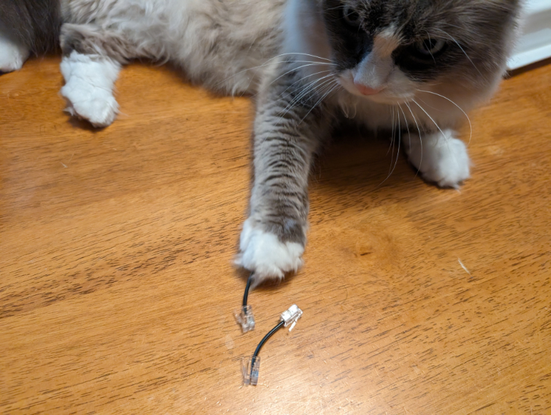
Telephone cables are... well, if you go shopping for RJ11 or RJ14 telephone cables, you might run into something odd. Some sellers, typically the more knowledgeable ones, may identify their cables as "straight" or "reverse." Even more confusingly, you will often read that "straight" is for data applications (like fax machines!) while "reverse" is for voice applications. If you consider that the majority of fax machines provide a telephone handset and are, in fact, capable of voice, this is particularly confusing.
See, the thing is, a reverse cable has the two ends swapped relative to each other. It's not like Ethernet, the RX and TX pairs aren't swapped, because there are no such pairs. Remember, the two pairs of a 6P4C telephone cable are used as two separate circuits. Instead, the polarity is swapped within each pair.
Telephone cables are wired in such a way that this is easy: in a 6P4C connector, the "first" pair is the middle two pins (3 and 4), while the "second" pair is the next two pins out (2 and 5). That makes them symmetric, so you can swap the polarity of all of the pairs by simply putting one of the modular jacks on the other way around. With Ethernet, not coincidentally, the "inner" two pairs still work this way. It's the outer ones that buck convention.
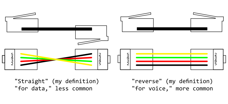
When the jacks are connected such that the pins are consistent---that is, pin 1 on one connector is connected to pin 1 on the other, we could call that a straight cable. If the ends are mirrored, that is, pin 1 on one end is connected to pin 6 on the other, we could call it a reverse cable.
With a telephone, we already talked about the hybrid situation: the two directions are not separated on the telephone line. We don't need to swap out RX and TX. So... why? why are there straight and reverse cables? Why do they have different applications?
Telephone lines have a distinct polarity, because of the DC battery voltage. For historic reasons, the two "sides" of a telephone pair are referred to as "tip" and "ring," referring to where they would land on the 1/4" connector that we no longer call a "phone" connector and instead associate mostly with electric guitars and expensive headphones. The ring is the negative side of the battery power, and the tip is the positive side. As standard, these are identified as -48v and 0v, because the exchange equipment is grounded on the positive side. Both sides should be regarded as floating at the subscriber end, though, so the voltages and positive or negative aren't that important. It's just tip and ring.
There is a correct way to connect a phone, but older phones with entirely analog wiring wouldn't notice the difference. When touch-tone phones introduced active digital electronics, polarity suddenly mattered, but you can imagine how this went over with consumers: some people had telephone jacks wired the wrong way around, and had for years, without any problems. When they upgraded to a touch-tone phone and it didn't work, the phone was clearly at fault, not the wiring. So, quite a few touch-tone phones were made with circuitry to "fix" a reverse-wired telephone connection. Besides, just to keep things complex, there were some types of pre-touch-tone phones that required tip and ring be correctly preserved for biasing the magnetic ringer.
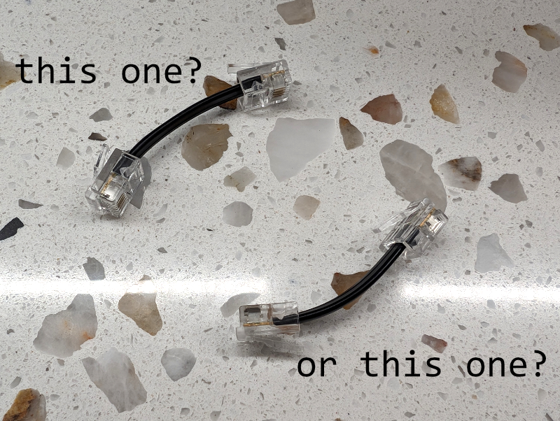
But wait... why, then, would so many sources assert that reverse-wired cables are appropriate for voice use? Well, there is a major problem of internet advice here. Look carefully at the websites that are the top results for the question of straight vs. reverse telephone cables, and you will find that they don't actually agree on what those terms mean. There are, in fact, two ways to look at it: you could say that a straight cable is a cable with the same correspondence of color to pin, or you could say that a straight cable has the two modular connectors installed the same way up.
If you think about it, you will realize that these conflict: if you attach both modular connectors with the latch on the same side of the cable, they will have mirrored pinouts and thus opposite polarity. To have a 1:1 pin correspondence that preserves polarity, you must attach the connectors such that one has the latch up and the other has the latch down. Now, this only makes sense if you lay your cable out perfectly flat, and for a round cable (like the twisted pair cables used for ethernet) you still wouldn't be able to tell. But telephone cables are flat, and what's more, the manufacturing process leaves a distinct ridge on one side that makes it obvious which way the connector is oriented. Latch on the ridge side, or latch on the smooth side?
There's another way to look at it: put two 6P4C connectors face-to-face, like you are trying to plug the two into each other. You will notice that, if the wiring is pin-to-pin, they don't match each other. Pin 2 on one connector is a different color from the adjacent pin 5 on the other connector. This isn't all that surprising, because we're basically doing the same thing: we're focusing on the physical orientation of the connectors instead of the electrical connection.
Whether "straight" refers to the wiring or the connector orientation varies from author to author. I will confidently assert that the correct definition of "straight" is a cable where a given pin on one end corresponds to the same pin on the other, but there are certainly some that will disagree with me!
Here's the thing: as far as I can tell, the entire issue of straight vs. reverse telephone cables comes from this exact confusion. Oddly enough, non-pin-consistent wiring (e.g. with pin 2 on one connector going to pin 4 on the other) seems to have been the historical convention. Many manufactured telephone cables are made this way, even today. I am not sure, but I will speculate it might be an artifact of the manufacturing technique, or at least the desire of those manufacturing telephone cables to have an easy, consistent way to put the connector on. Non pin-consistent cables are often articulated as placing the connector latch on the ridge side of the cable at both ends. Which makes sense, in a way!
The thing is, these cables, standard though they apparently are, will reverse the polarity of the telephone line. If you connect two with a mating connector, the second one might reverse it back to the way it was before... but it might not! mating connectors are made in both straight and reverse variants, although in this case straight seems much more common.
And I believe this is the whole origin of the "data" vs "voice" advice: telephones, the voice application, rarely care about line polarity. Data applications, because of the diversity of the equipment in use, are more likely to care about polarity. Indeed, for true digital applications like T-carrier, the cable must be straight. The whole thing is perhaps more succinctly described as "straight vs. don't care" rather than "straight vs. reverse," because as far as I can tell, there is no true application for what I am calling a reverse cable (one that does not preserve pin consistency). They're just common because of the applications in which polarity need not be maintained.
But I would love to hear if anyone knows otherwise! Truthfully I am very frustrated by this whole thing. The inconsistency of naming conventions, confusion over applications and the history, and argumentative forum threads about this have all deeply unsettled my belief in the consistency of telecommunications wiring.
Also, if you're making telephone cables, just make them straight (pin-consistent). It seems to be the safer way. I've never had it not work!